Girder Forks
The
overall assembly of the individual parts of a typical Girder suspension system
can be quite varied. For example the links can be situated on the ‘inside’
or the ‘outside of the main fork legs. The links themselves can be fabricated
from tubing or from flat bar stock or from castings. It’s not uncommon to see
more than one link attachment method used on a single girder. You’ll sometime
run across units that use continuous pivot shafts in the forks but rigid link
pins on the yokes and vice versa. You’ll also see units where the upper links
may be mounted inside the fork legs while the lower links are mounted outside.
On some customs you’ll see forks with only one central upper link and two
lowers or one central lower and two uppers. Occasionally you’ll find a fork
where the shock or shocks are mounted below the lower yoke and attach to the
rear legs in a modern adaptation of the old Vincent configurations.
Folks
are finally catching on to the fact that a good mono-shock mounted lower in the
forks reduces the height of the bikes center of gravity and permits one to use
very short links while cleaning up that area ahead of the steering stem.
Earlier
we alluded to the fact that in the realm of chopper building there are often
trade-offs, adjustments and compromises made that create a balance between
strength, practicality, form, function and simple appearance considerations
until just the right balance of critical factors, tempered with artistic
judgment result in a final design concept that not only ‘works’ but also
looks good at the same time.
All
of us at one time, or another, have walked through a bike show and seen machines
that defy the imagination. We’ve also made mental notes about which particular
bikes were really ‘roadworthy’, or could actually be driven on a daily basis
and which one’s were pure ‘eye-candy’.
If
you decide you want to build Girders your design talents will be pushed to the
limit since I cannot possibly imagine where artistic judgment and good
engineering sense are put more to the test than in building one of these front
ends that will not only handle the real road on a daily basis but look good
while doing it.
From
my personal perspective I rank fork system strength and functionality foremost
and try to figure out a way to make it all look attractive and proportional with
the rest of the bike secondarily. To be able to do this you have to have the raw
materials and other components in hand to make valid decisions based upon not
only sound engineering principals but also artistic visual comparisons of
various potential assemblies. In other words you have to be able to actually
see, feel and ‘experience’ the parts you want to experiment with. You just
can’t pick parts from a catalog and expect anything to look proportional.
You’ve got to have the stuff in your hands before you begin the design and
fabrication process. As much as I like ‘plans’ this is the one area where
real parts will far outweigh anything you see on paper.
Fortunately
buying a lot of parts for a potential Girder project isn’t all that expensive
and to start with you really only need a single ‘example’ of each item for
each component assembly you’re planning to experiment with and you don’t
need fancy top of the line parts to start with during the planning and mock-up
stage.
To
give you an example of what I’m talking about try this little experiment. Take
two sections of 1” tubing about 36-inches long and polish one to a bright
luster. Paint the other one with black paint, to simulate powder coating, and
put them side-by-side. The polished tube will look considerably ‘narrower’
or smaller in diameter than its painted counterpart. If it were chromed it would
look even thinner. In this instance
if you were after a certain ‘look’ for a set of forks that were to be
powder-coated you would have selected slightly smaller tubing, 15/16” DOM for
instance, so it would have the same visual ‘weight’ or ‘size’ as a
skinny looking piece of chromed 1” tubing.
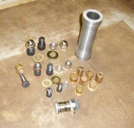
The
picture below illustrates a variety of common fasteners and fittings that you
might be using on a Girder fork system. The steering neck and stock rocker bolt
are to provide scale.
Figure
11
The
larger bolts in the upper left-hand corner are 5/8” cap screws and in the next
row are half-inch and then down further 3/8” fasteners. The bronze bushing
range in size from half-inch to ¾-inch in inside diameter and the washers and
spacers shown are all grade-8. Some of the cap nuts are nickel-plated and some
are stainless steel.
As
you can see there is a huge ‘visual’ difference in size and mass between a
5/8” cap nut (acorn nut), for instance, and a one-half inch cap nut even
though ‘on paper’ there is only a one-eighth inch difference in diameter and
a lot of people would opt for the larger fastener for safeties sake even though
it would look pretty out of place on a girder made from 7/8” tubes for
example.
DOM
Tubing Schedule
The table below lists some of the more
commonly used sizes of DOM tubing that you might need if you’re building
Girder forks.
|
O.D. |
Wall
|
I.D. |
Wt./Ft. |
Remarks |
|
|
|
|
|
|
|
5/8” (0.625”) |
.120 |
.385 |
0.647 |
|
|
|
.125 |
.375 |
0.668 |
Bushing Tubing |
|
|
.134 |
.357 |
0.703 |
|
|
|
.156 |
.313 |
0.781 |
Tap for 3/8-16 UNC
(5/16” Drill. .3125) |
|
|
|
|
|
|
|
3/4" (0.75”) |
.109 |
.532 |
0.746 |
Tap for 5/8-11 UNC
(17/32 Drill, .53125) |
|
|
.120 |
.510 |
0.807 |
|
|
|
.125 |
.500 |
0.835 |
Bushing Tubing or
Shaft Sleeve |
|
|
.134 |
.482 |
0.882 |
|
|
|
.156 |
.438 |
0.990 |
|
|
|
.172 |
.406 |
1.063 |
|
|
|
.180 |
.390 |
1.097 |
|
|
|
.188 |
.375 |
1.186 |
Bushing Tubing or
Shaft Sleeve |
|
|
.203 |
.344 |
1.186 |
|
|
|
|
|
|
|
|
7/8” (0.875”) |
.120 |
.635 |
0.969 |
|
|
|
.125 |
.625 |
1.002 |
Bushing Tubing or
Shaft Sleeve |
|
|
.134 |
.607 |
1.061 |
|
|
|
.148 |
.579 |
1.150 |
|
|
|
.156 |
.563 |
1.199 |
|
|
|
.180 |
.515 |
1.337 |
|
|
|
.219 |
.312 |
1.242 |
Tap for 3/8-16 UNC
(5/16” Drill, .3125) |
|
|
.250 |
.250 |
1.335 |
|
|
|
|
|
|
|
|
1” (1.00”) |
.120 |
.760 |
1.128 |
|
|
|
.125 |
.750 |
1.169 |
Bushing Tubes or Shaft
Sleeve |
|
|
.134 |
.732 |
1.239 |
|
|
|
.156 |
.688 |
1.406 |
|
|
|
.165 |
.670 |
1.473 |
|
|
|
.172 |
.656 |
1.522 |
Tap for 3/4-10 UNC
(21/32 Drill, .65625) |
|
|
.180 |
.640 |
1.576 |
|
|
|
.188 |
.625 |
1.630 |
Bushing Tubes or Shaft
Sleeve |
|
|
.219 |
.562 |
1.827 |
|
|
|
.238 |
.524 |
1.937 |
Tap for 5/8-11 UNC
(17/32” Drill, .53125) |
|
|
.250 |
.500 |
2.003 |
Bushing Tubes or Shaft
Sleeve |
|
|
|
|
|
|
|
1-1/8” (1.125”) |
.120 |
.885 |
1.288 |
|
|
|
.125 |
.875 |
1.335 |
Bushing Tubes |
|
|
.134 |
.857 |
1.418 |
|
|
|
.156 |
.813 |
1.614 |
|
|
|
.180 |
.765 |
1.817 |
|
|
|
.188 |
.750 |
1.881 |
Bushing Tubes |
|
|
.219 |
.687 |
2.119 |
|
|
|
.250 |
.625 |
2.336 |
Bushing Tubes |
|
|
.313 |
.500 |
2.710 |
Bushing Tubes |
|
|
|
|
|
|
|
1-1/4” (1.25”) |
.120 |
1.010 |
1.448 |
|
|
|
.125 |
1.00 |
1.502 |
Bushing Tubes |
|
|
.134 |
.982 |
1.597 |
|
|
|
.156 |
.938 |
1.823 |
|
|
|
.180 |
.890 |
2.057 |
|
|
|
.188 |
.875 |
2.132 |
Bushing Tubes |
|
|
.219 |
.812 |
2.411 |
|
|
|
.250 |
.750 |
2.670 |
Bushing Tubes |
|
|
.313 |
.625 |
3.126 |
Bushing Tubes |
|
|
|
|
|
|
Keep
in mind that this isn’t a comprehensive list of tube sizes just the more
commonly available size combinations that work well with Girder fabrication.
To
Be Continued………………………………………

| Main Page | Terms of Use | Security and Privacy | FAQ | Contact |
Copyright © 2003-05 Chopperhandbook.com, Chopperbuilders.net, All Rights Reserved